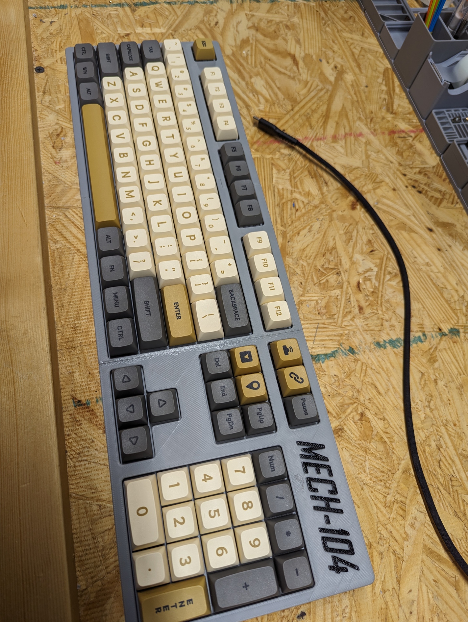
Mech 104
Links:
https://www.thingiverse.com/thing:4205065
https://www.printables.com/model/413280-mechanical-keyboard-mech-104
https://cults3d.com/en/3d-model/gadget/mechanical-keyboard-mech-104
https://circuitpython.org/board/vcc_gnd_yd_rp2040/
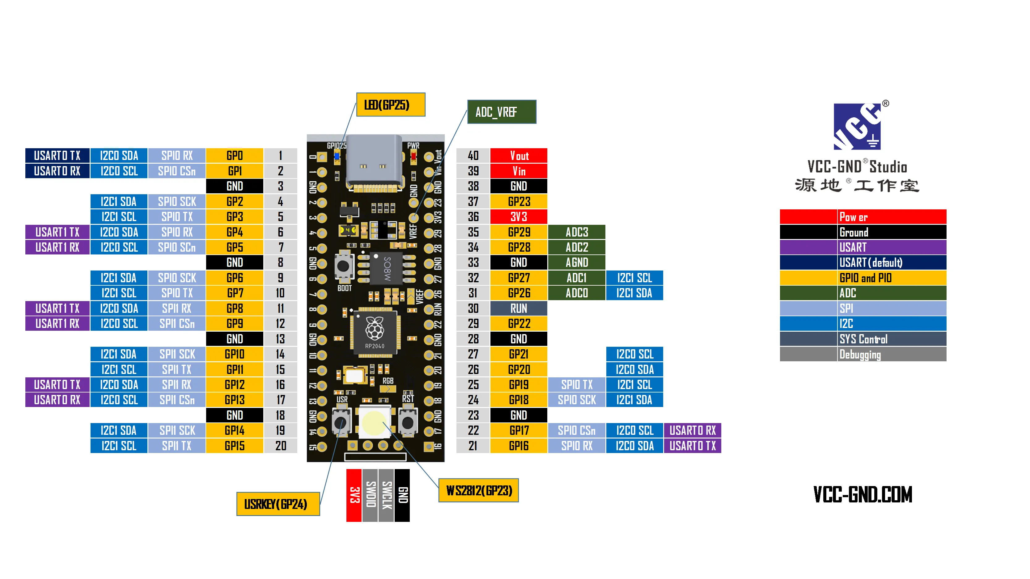
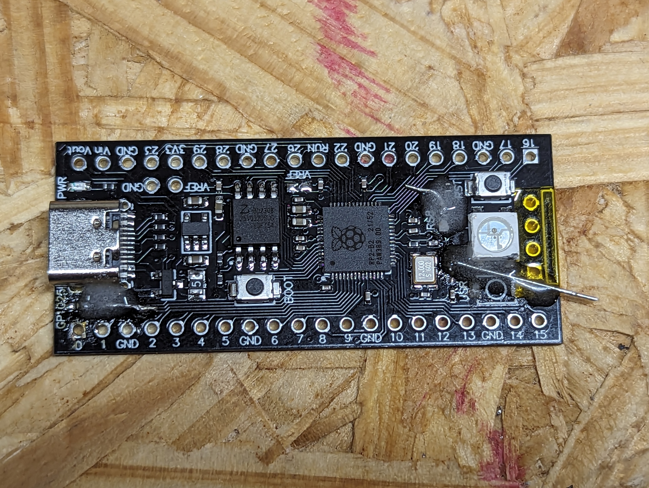
Board: YD-RP2040, a raspberry pi pico clone.
I went into this build not realizing that the above links are for QMK using a Teensy board. I thought it would be an easy build using the RP2040 with KMK.
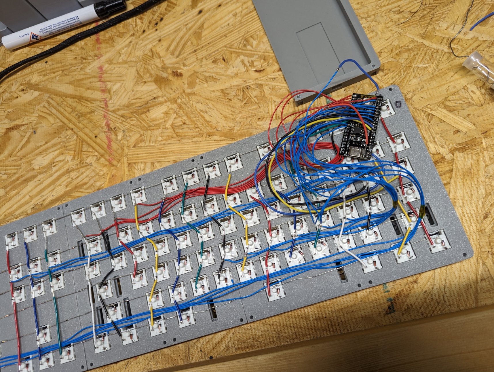
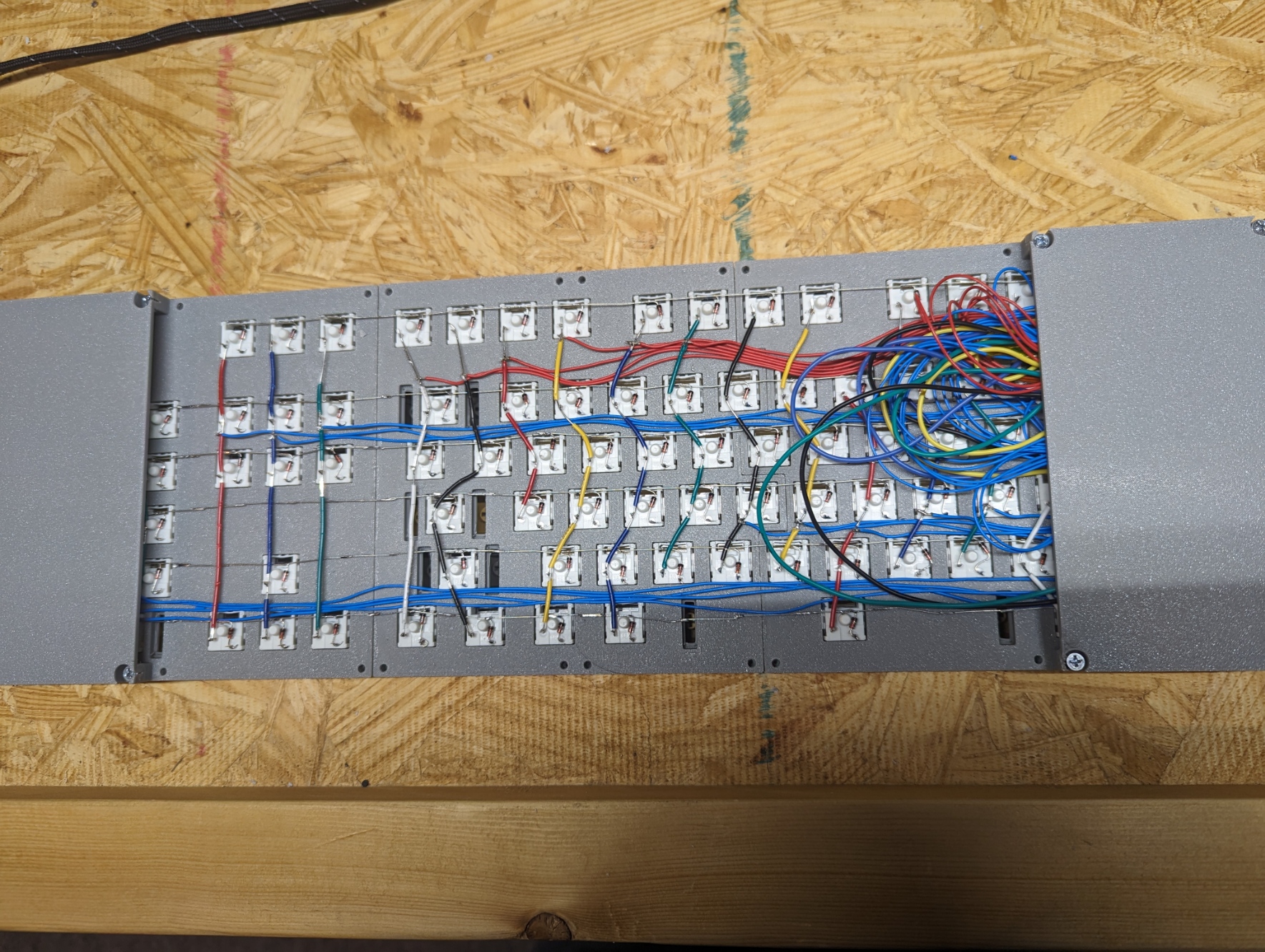
This is my 3rd keyboard, the first being numpad, then a sick68 + numpad, and now this full size MECH-104. I’m using it right now to type this.
The soldering layout in the above links assumes you’re using QMK. With KMK it assumes you are using a correct grid. It took me a while to realize you have to use KC.NO to fill voids.
I’ve built multiple projects with arduinos / pis / microcontrollers the past few years but got stuck trying to figure out exactly what pins this board had. I could not find any real documentation and it was only after slowly reading the KMK docs found out you can query your board and see exactly how your pins want to be addressed.
The small scale code test ran fine when I was testing a 2x2 matrix. Once I saw that worked I filled out the rest of the pin names all the way up to board.GP28,. When I ran the code again nothing worked. I had to slowly test pins all the way up and realized that the code stopped working when I used board.GP.24,
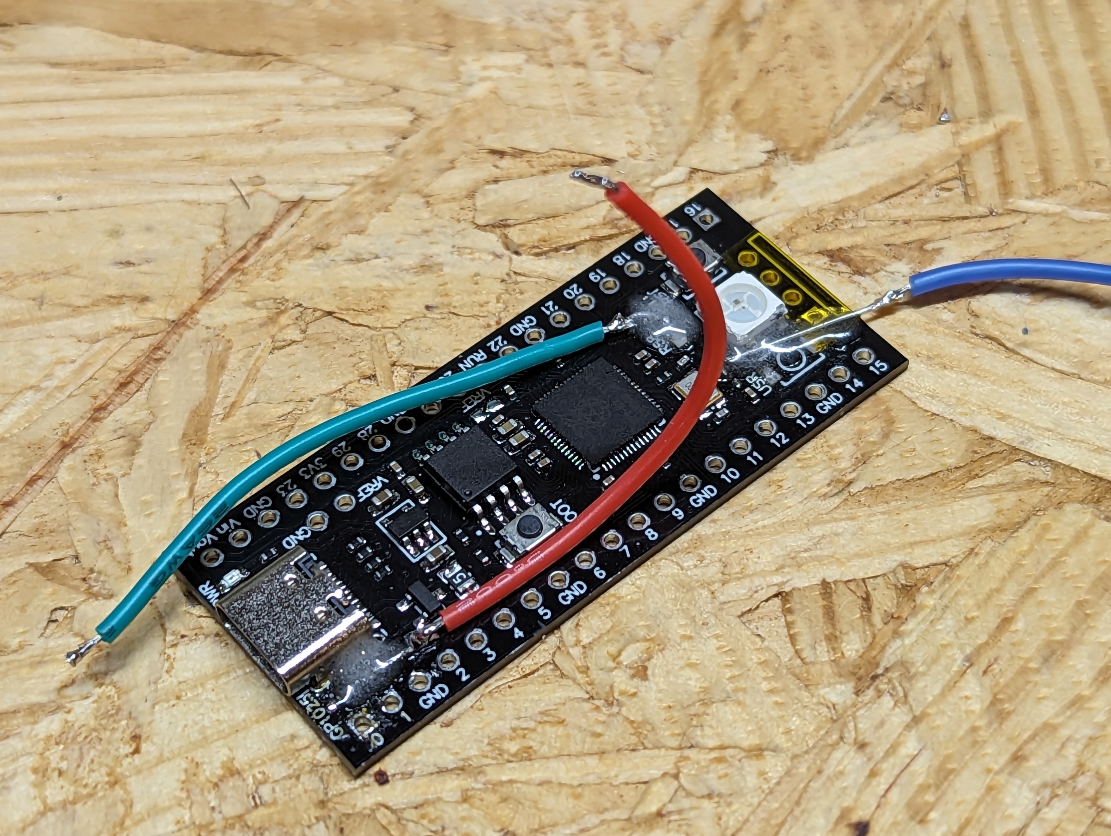
GP24 is the USRKEY and GP25 is the LED. Both of these need to be desolderd and a tiny wire attached to be used as a PIN. More on this below.
I finally found out how to view the board over Putty and enable the debugging code so I could see where the board was getting caught up and how to print out the pin names.
keyboard.debug_enabled = True To enable viewing
print(dir(board)) To pirint out the pin names
The correct pin names were board.LED and board.BUTTON.
After that the only thing left to do was correct the keymap according to the soldering layout in the Thingiverse pictures.